

Ian
-
Content Count
104 -
Joined
-
Last visited
Posts posted by Ian
-
-
i recently purchased an 1992 Monterey 256 with twin 3.0 engines. The right side engine is in real bad shape, so i decide to buy a new one.
Are they both std rotation? since i just ordered a new engine and didnt know that with twin engines one can be reverse rotation.
Need help newbie here!!!
Hi,
Generally most twin motor installations rotate in the same direction (left hand a.k.a standard a.k.a conterclockwise).
The counter-rotation of props is done by your sterndrives and / or the way you set up linkages. (This depends on the model of your sterndrive)
You don't mention what type of sterndrive you have (Alpha, Alpha GenII, Bravo2 or Bravo3)
If you are replacing BOTH your engine AND your sterndrive and it is an Alpha drive, you will need to specifcy rotation of the drive BUT this will be part of the model / serial number of the drive
Here is a link and extract from a sterndrive company
http://www.sterndrives.com/414alphaone.html
(make sure you select the correct drive page)
Trust this helps some
Regards
Ian
(from sterndrives.com website)
A note about ROTATION
Do not confuse engine rotation with sterndrive or propeller rotation
ALL sterndrive Mercruiser Engines are left hand (standard, counterclockwise) rotation.
Most single engine boats use a right-hand rotation drive unit meaning that
the propeller rotation is right-hand (standard, clockwise) rotation.
Counter rotating drives are left-hand (counter, counterclockwise) propeller rotation.
Counter rotating drives have only been around in numbers for the last few years.
The advantage of having two drives rotating in opposite directions are
increased speed, improved slow and high speed handling, better course tracking,
more level ride, improved fuel economy and easier docking.
NOT ALL DRIVES CAN COUNTER ROTATE!
The drive must be specifically designed to be a counter rotation drive.
Attempting to run a standard rotation drive in a counter rotation direction
will positively destroy the drive in just a few minutes.
In most applications the RH (standard) drive is mounted on the starboard side.
The LH (counter rotation) drive is mounted on the port side.
The LH drive must have a LH propeller. The LH shift cable must be reversed at the binnacle to pull instead of push
for forward gear. Most controls allow for either direction by simply repositioning
the cable mounting location and attachment.
Always use extreme care when reinstalling the drives that they are properly
installed on the correct side or extreme expensive damage will occur.
Bravo Drives are bi-directional.
Rotation direction is simply determined by the shift cable direction
and no damage will take place by reversing the running direction
or by installing the Bravo drives on different sides. Again, the RH propeller is
usually installed on the starboard side and the LH propeller is usually
installed on the port side.
Use caution when attempting to operate the boat for the first time after
drive, shift cable, or propeller work has been done. Tie the vessel firmly
to a strong dock and test the shift for proper direction.
Improperly
installed props, drives or cables can make the boat go in reverse instead
of forward causing severe damage, injury or death. Just check it.
-
Thanks for the reply I will have to look through all the paperwork that came with the boat yet again as I think i remember seeing a booklet on the smartcraft guage but thoght it was just included in all packets as we have faria guages. I wonder if we could have had it equipped but the guage was never installed? I wonder if the most could help to determine if it was so equipped? The speedo does have a disply but the only thing it seems to display is an intermittant hour glass and constantly the engine hours. No change when warning beeper goes off. I will have to ask the marina if they can retro fit a display thet would be able to advise which condition it is since it seems by the chart you provided it is either 2 beeps a minute or constant. I thought in years past i had one thet was 3 beeps per minute but i could be wrong. This last weekend I used only battery 1 (I usually use both position on the battery shut off switch) and got no faults. I may try battery 2 the next time to isloate if it is a battery issue. I am also changing oil, doing the drive service and winterizing next time I go to the lake so I can have them see what codes are stored.
Hi again,
Here is a link to FAQ's on Mercruisers site http://www.mercurymarine.com/service-and-support/storage-and-maintenance/faqs/smartcraft/
You will need to check your engine series but I think any MPI series motor from 2001 is "smartcraft compatible"
Whether this means you actually have it fitted is a different story.
"Compatible" means all the digital signals are available from the ECM on the motor. From there, it depends on the harness fitted and the gauges used at the time of original engine installation. It is possible to connect the motor upto digital gauges, analogue gauges or a combination of both depending on the cable / gauge configurations used
Faria do make a range of gauges that are smartcraft compatible. I suggest you find the model number of your gauge and go look at their website.
Here is a link to find your gauge model number if you dont have access to the rear of the dashboard http://gaugefinder.faria-instruments.com/
From there, search for your gauge and possibly an owners manaul for it.
On my 2008 MPI 350 (I don't know who the manufacturer of the gauges are. Mercury don't actually make the gauges), there are a few rubberised buttons below the tachos which let you scroll through the smartcraft displays.
By the sounds of it, you don't have smartcraft fitted.
How much difficultly, time or cost is involved, I don't know. You would need to talk to a Mercruiser dealer.
Whilst it might be "nice" to have it fitted, it will cost you $$$ (and frankly, it won't add 1 cent to your resale value -sorry!)
I could well be much cheaper just to have the tech check the fault codes with a handheld scanner.
Cheers
-
Is there a chart to decipher what the warning beeper is indicating by the sequence? I periodically get a warning that the marina says is a low voltage situation. When it goes off it is always under acceleration just before comming on plane. One tech said the merc 496 is a battery power hungry motor and if the batteries are not tip top perfect it could set off the warning. The last 2 times I watched the voltage guage and it never went below 13 volts. It happens more at the end of the season on chilly mornings. I have noticed that the captains call exhaust really puts a drain on the voltage meter but I have gotten the warning with exhaust shut off during acceleration trying to avoid the beeper as once it goes off you have to shut motor off to clear it. First they thought it was indicating low gear lube but resevoir was full and disconnecting that sensor temporarily did not make it go away so that sensor was ruled out and they said bad battery. This is only the second season for these batteries and first set lasted from 2003 to 2010. I have looked in all the books and manuals that came with the boat new and see no chart for what the possible indications are.
Hi cvettr
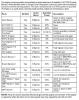
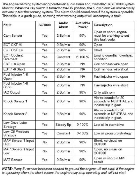
Please see attached pics of charts corresponding to error codes.
The SC1000 column refers the Mercruiser Smart Craft instumentation package. (If you had this fitted, it would trigger a fault message in your display)
I am not a mechanic, but as far as I understand it, there is there is no "sequence" of beeps you can use to determine the fault which is causing it.
Basically, most faults are indicated by a double beep, while most "serious faults" are indicated by a continuous beep / tone.
(I think the continuous beep / tone faults are the ones that are likely to trigger the reduced power "limp home" mode)
To understand what errors are being detected, you need to have your ECM scanned.
First option would be a genuine Mercury service dealer.
Some other good marine mechanics also have scanners - you just need to ask if they have one to detect / rectify faults for your engine
As for the voltage drop and any effects it has on the ECM, I don't know enough about it to comment. Maybe someone else here on the forum can help. Failing that, borrow a battery from one of your fellow boaties and swap it to see if the problem persists.
Good luck
Regards

-
So did any of the 298 SS boats come with Gaffrig style controls??
I don't hate the Merc shifters, it's just they're hard to finesse. How difficult would it be to make the conversion?
Hi,
Do you have mercruiser DTS?
If yes, it is a simple process as everything is driven electrically, no solid cables are used to connect the controls to the motor/s
Mercruiser call it Zero Effort - DTS. They sell as kits with instructions, mounting templates, controls, cables etc
If you search for that online you will find lots of suppliers, forums etc.
They are pricey - a 2 engine setup is listed around the $1800 - $2000 mark (kit only, no labour to install)
If you currently have a mechanical cable setup, I don't know how you would go about it but suspect the biggest issue will be if you are able to use the same mechanical cables and connectors.
The gaffrig website does list a "mercruiser stern drive cable adaptor", so it might be a easy job, altough if you physically have to relocate the control position, I'm guessing you will need new cables and routing.
Contact them and see how helpful they may/may not be
Regards
Ian
-
Waytam
I had been waiting to see if someone else with a much better understanding would respond. No-one has, so here a few ideas to hopefully chase down your problem.
To answer your specific question, I don't know how you can check the trim sending unit in service. If you disconnect it, the pump won't work. The pumps used on mercruiser only have 3 wires entering (up, down and neutral) so I'm guessing the monitoring of the position of your trim is handled someplace other than the pump motor itself. Most likely will be the ECM (engine control manual) of which I know nothing about except all your instrumentation comes from / goes through there.
You don't say if it is a mercruiser or volvo. I have mercruiser but assume volvo would be similar.
If you purchased the boat new, you should have received an installation manual for your engines. (I'm not sure if you can find a copy somewhere but if it helps I have the one for the Mercruiser 350MAG-MPI - let me know if you need a copy). I assume the trim pump assembly/s would be pretty similar across most engine variants. (See attached pics).
I do have some suggestions that might be helpful. If they don't work, I'm guessing the only way you will resolve your problems is to get the ECM checked out. Some ECM's also store fault codes which can be diagnostically checked by someone with the correct equipment (not sure about year models in 2004)
Many strange problems in DC systems can come from a loose wire or two.
First item should be to make sure all the neutral wires in and around the trim pump assembly are clean, free from corossion and tight.
Next, make sure all the neutrals in and around your engine block are similarly clean / tight. Check the mounting of the ECM and its neutral wire connection into the 'box'. There might also be a 'tie' wire to the engine block to check as well.
Finally it would also be a good idea to check battery neutral and main connection to engine mount.
Another check to do is to understand what voltages happen at the rear of your gauges.
Does the 12V supply completely disappear? or does it drop to a lower value which the falls below the guage threshold?
When testing this, don't use the gauge nuetral wire connected to the guage itself, pick another neutral - say your cigarette lighter.
I don't think you have a short in your pump motor otherwise the fuses would be blowing.
It may also be possible to have a short in your instrumentation wiring harness but i think this would be less likely as more than 1 gauge is being affected.
Finally, I am intrigued by your item #6. If you disconnected the engine battery, trim would go dead, everything would go dead and your motor would have stopped (if it was running). What batteries are you referring to?
Good luck
-
Dan,
Thanks for the suggestion. I actually went down to the boat on Saturday (after typing the message) and checked the breaker and it was fine. Also had some help in checking the electricals and discovered power everywhere except at the windlass.
Turns out the negative cables at the battery was loose and that what was causiong the windlass stoppage! Those dam wingnuts became loose!
Also: Discovered two wire attachments for the main helm breaker and main cabin breaker (located in compartment on reat starboard side) were just about coming undone due to the nut being very loose.
In any event, I would still like to know how the windlass is actually wired and whether there is a solenoid somewhere on the boat?
Ken
Hi,
Here is a link to the Lewmar manual http://www.lewmar.com/assets/img/dataset/Manual-Sprint_600.pdf
See page 13 for wiring information
You said you have foot switces and a helm switch, therefore you must have a control box. This also contains your "solenoid". You won't see a "solenoid" like on a starter motor for your engine/s. It should be about the size of 2 or 3 cigarette packet stacked on top of each other
(Where you don't have footswitches see page 12)
I don't have a 270 so I can't comment where it would be located on your boat but usually they are not too far from the windlass itself and / or the foot switches. I would try tracing the wires from the foot switches first. It should be fairly easy to identify with heavy guage battery (+ and -) entering and leaving with lighter guage 'switch' wires for your helm / footswitches entering
Hope this helps some
Regards
Ian
-
I am new to boating & have what may be a dumb question.
I have a 2002 242 monterey. It has a perko battery switch and 2 deka starting batteries. Question - if I want to go and anchor somewhere for the day and /or night and use lights and radio, should I leave the selector switch on 'All' or switch to 1 or 2 and try and save one battery as a starting battery. My concern is because both batteries are 'starting' batteries and not 'deep cycle'
Tks
Cam
Hi,
Firstly, I'm assuming you only have 1 motor, the switch / 2nd battery is your house battery, and you have a battery charger
It really depends on what sort of current drain you want to pull out the battery, the rate at which you drain it and how often you do this (once a week, once a month?)
If all you will ever do is a few lights and your stereo then you shouldn't have any problems running a "start" battery as your house battery.
If you started running some big loads - inverters, refrigerators, tv etc. then you might need to re-consider using a "deep-cycle" battery with increased capacity for the house battery.
With the dual switch you describe, there shouldn't be any proplems using a "start" battery for battery1 and a "deep cycle" battery for battery 2 (if you want). The only important thing is they must both be the same "construction" i.e both lead-acid OR both AGM.
Generally, you should only use battery 1 as a start battery and battery 2 as your house battery. The "both" position should be used when you want to recharge both batteries whilst your engine is running. When anchored, keep the switch in battery 2 position. If you find your house battery is always running flat, consider changing it to a bigger capacity and /or adding a second house battery (connected in parallel) with battery 2.
Using a "deep-cycle" battery wont increase any power, it just means it is designed to be discharged / recharged more often AND 'recover better' from a deeper discharge than a "start" battery
Finally, if/when you change-out your house battery, yes replace it with a deep-cycle type but unless you are having troubles, the current setup should work fine
Hope this helps some
-
Hi Ian
Most likely it has no affect on attracting Bass. Though, this weekend I could have drawn a diagram of a similar installation on hook nearby, removed the offensive noise maker and gladly shipped it off to 180FS in Nashville with my compliments. BTW, Ian how's boating life down under, you guys are always entertaining.
Cheers
Alan
Hi Alan,
It's winter here - but not like winters in the north of the US and Canada (thankfully)
Temperatures (near Sydney) typically range from 5C overnight to 18C during the day (40F - 65F)
One of the best times of the year for boating - magical early morning mists - and less crowds. Sometimes I'm the only boat in a bay.
This time of the year there can be some BIG swells off the coast - so mostly rivers and bays
Still get the die hard fishos going past at 4am in their little tinnies and old 2 strokes - maybe they're going bass tubing?
Regards
Ian
-
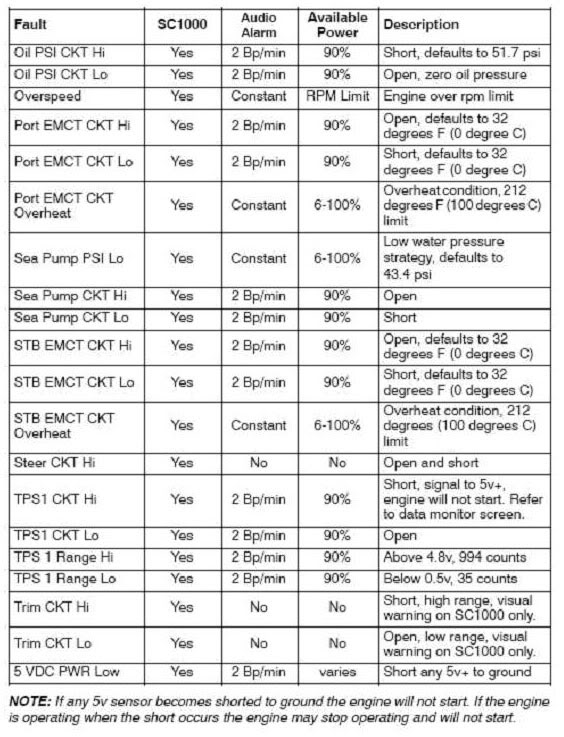
I'm not one of these people who feel the need to provide music for the entire cove, but I would like to add a little needed low end sound to my stereo and am wondering how a self-container bass tube would work. I don't have the need or desire for separate subs, amps and component speakers, just looking for a little extra bottom sound. Has anyone done this? If so, how was the result?
This is what I'm looking at getting:
http://ecx.images-am...L500_AA300_.jpg
Thoughts?
Does it help catch bass?
(sorry - I couldn't help myself)
Regards
-
Hi
Wiring diagrams can be found the Owners Manual - you can download from the forums here under Sport Boat Owners Manual - wiring diagrams start at page M-32
The BROWN/RED wire is the +12V which comes via a fuse. This is the AUTO bilge pump and should go to one side of your float switch. The other side of your float switch should then go to your bilge pump. I am assuming the wire leaving the float switch is also BROWN/RED
The RED wire is the +12V from the rocker switch at the helm. This goes directly to your bilge pump. It does not go through the float switch.
The BROWN/RED (from the float switch) and the RED (from the helm) wires are connected together at the pump
The BLACK wire is a bit of a mystery. According to the wiring diagram it should be yellow. Either way, it should be the -12V and should be connected to the other side of the pump (i.e. the side that DOESN'T have the brn/red + red wires on it)
Your pdf is electrically correct. I don't have a 190LS but think it might be more likely the 2 positives are connected at one side of the motor rather than being joined in the harness as shown in your pdf. It doesn't make any difference electrically
Hope this helps some
Regards
I understand from Monterey that the 190LS does not have a three way switch on the dash for the Bilge Pump and the two position rocker functions as the on for manual and then off. When in the off position the float switch is feed by a fused line direct from the battery. I had removed the connecting wires from the float switch and bilge pump prior to undersatnding this and am struggling with rewiring this, (I know this should be simple!!). In the bilge area there are three wires entering from the harness; black, brown and brown/red. Can someone confirm my wiring diagram as to how this should be wired for a bilge bump and seperate float switch and the designation for each of the incoming harness wires....

Thanks
-
Brand new 260 SCR. Turned on the water pump breaker the other day to use the transom shower. While the shower worked water was also pumping out from a discharge at the rear. Once I turned off the shower the water pump stayed on and water continued to pump out of a rear discharge. The only thing I did different was remove the water fill cap and fill the tank. This is the first time this happened. My theory is the pump is not priming correctly. Am I correct and are there any suggestions?
Hi,
If your transome shower was working correctly then your fresh water pump is priming correctly
Sounds like you have a water leak somewhere.
Which discharge was the water coming from? - check the Monterey owners manual. It has labelled pictures of the hull showing all of the discharges, vents etc.
How much water is in your bilge? If you have a leak of the freshwater system and it is going into your bilge, the automatic bilge pump could be operating.
Try shutting all the taps, showers etc. off and open your engine hatch so you can see in the bilge.
Turn on the water pump. You should be able to hear the pump running briefly to 'pressurise' the system and then stop.
If it doesn't stop, you have a big leak.
If it stops and starts, then you have a smaller leak
Regards
-
This is great and thank You for your help! I think it is a factory installed unit and there is no power at the terminal of the Windlass. It does not have any foot controls either. I did not realize that the Red button at the Battery switch area was a trip system. I will take another look at it when I get back to the lake and let you know. I really aprreciate it.
Here is an image of a typical windlass breaker, similar to the one in my 330SY
Regards
-
My 2008 330SY camper covers are starting to show their age.
The north facing clears (which are exposed to the sun all day) all have developed a greyish, milky like build-up at the perimeters where the platic is stitched to the fabric
The main viewing areas have also developed 'pitting' with the same build-up.
The other clears facing other directions do not have it.
Any ideas on how to get rid of this build-up as it makes vision through them difficult
I have tried 'plexus' and '3M plastic restorer' without any success. The milky build-up just will not budge
Thanks
-
It has a carb. The engine runs great/smooth. Has lots of power. Starts quickly. Only every now and then it will not shut off. When it does happen, the kill switch also doesn't work and so I turn the key slightly like if I wanted to start. Then I can go back to off position with the key and the engine shuts off.
So far I've only replaced the ignition.
Sounds like a strange problem.
I would suspect there might be a problem in the engine control module.
It is very unusual that the kill switch isn't working as this is obviously a major safety feature. I don't think its the kill switch because if this went open circuit (broken) you wouldnt be able to start the motor in the first place).
If its not a timing issuing, might be time to visit the volvo / mercruiser dealer to check the ECM
Any other responses?
Reagrds
-
I hope someone can help! I have a 298SC and there is no electrical power at the Windlass/Anchor. The boat has a reset button by the battery switches and I have power too and from that button. Could there be some sort of relay between that reset button and the Windlass? This is a great boat and it would be even better if I can get to the bottom of this problem. Any help would be appreciated.
Hi,
I don't have a 298 but here a few comments.
You say you have power at both sides of the reset button.
Do you also have power at the terminal on the windlass?
Was it factory fitted or aftermarket?
What do you mean by "button"?
There are usually 2 parts to a windlass circuit breaker. A "button" and a "lever". The button is a trip system to stop power. The lever is the actual part that operates the circuit breaker has to be pushed up and hidden from view for it to operate correctly. Sometimes these need a lot of effort to reset
Most windlasses use 2 circuits
1 = the main power to the windlass motor. These are usually quite thick cables. The +ve cable is connected to the circuit breaker mounted at your battery switch panel
2 = the control power from the helm switch. This power usually operates a solenoid (either internal or external depending on the brand / model of the windlass). These are usually thinner cables and may number upto 3 cables (or more if you also have deck mounted foot switches fitted)
Depending on your set up, there maybe a circuit breaker in the "control wiring". This will usually only be a 5amp or 10amp. In the 298 factory fitted option there is usually a push button covered in rubber fixed above the rocker switch to operate the windlass.
Finally, it is also possible the power wiring and the control power come from different batteries and it may be possible you need both your battery switches in the 'on' position. (I learnt this the hard way. Manually lifting 50' of anchor chain is hard work)
Hope this helps some
-
After engine is warm, occasionally the engine will not shut off. Also, the engine shut off switch does not work.
Any ideas why this is happening some times?
What type of motor is it - fuel injected or carburetor?
When you say the motor will not shut off or the shut off switch doesn't work - how long does the motor stay on? - seconds? minutes?
Does it run extremely roughly when it is trying to shut down?
So how do you shut down if it keeps running?
If it is a carburetor motor - it sounds like an issue of very bad timing adjustment
When was the last time the motor was serviced?
-
I have a 1994 225 cuddy w/ Volvo Penta 5.7 DP and I am unable to remove the props! Service work is up to date from winterization! There is grease present when I remove the propeller cone and washer but the propeller will not budge! I am hoping that I am missing a step in removal and that it is not "frozen"!! I have read the manual 6 ways to sunday and searched various websites but still no luck! Any help would be greatly appreciated!! Thanks
Hi
You might need to invest in a prop puller similar to http://www.proptopuss.com/20067_471.asp (singles) or http://www.proptopuss.com/20067_819.asp (duos)
The second one is adjustable to remove the back prop first, then the inner prop second
Never used one before so can't comment on the effectiveness
Might give you a few ideas for something to look for
Regards
-
FWIW, I called to get pricing on mans for my 180FS 4.3L Merc w/ Alpha1 O/D:
Owners man: $26.95
Service man: $84.95
Parts man: $17.95
And if you need a service and/or parts manual on the outdrive, those are separate mans and priced the same.
WOW - you spend thousands on a motor and an outdrive and they want to stick you with another $130 for manuals for engines AND another $130 for drives
There are several manuals available on line at the link I posted above but unfortunately they only go to the early 2000's
Regards
-
New to boating. Bought 302 with twin 5.0. What process for engine flush while boat is in lift. Thanks.
Hi,
Go to this site http://www.4shared.com/dir/8iGasxP0/sharing.html
Look for Mercruiser Service Manual #24 and download
This manual should cover 5.0L from 1998 upto mid 2001
It has all the procedures you need depending on type of motor, pickups etc.
It is a BIG document (800+ pages), but you can electronically search
Regards
-
Hi
You will need to check with Volvo for your actual motor / model
I think you will need to have an interface box added to your motor (if its not already there) This is unlikely, as Volvo would have only fitted if you had the Volvo EDC system. Back in 2008 it was standard on diesel motors but an option on gas motors.
I suspect you will need big pockets to have it retro fitted - probably a lot more than your Garmin 441S.
Good luck!
-
I am tired of cleaning the carpet in my 282CR! Has anyone changed the flooring to either laminate or ??? Any suggestions, pic's would be GREATLY appreciated!
Hi
My 330 came with a laminate floor as standard.
I don't think it is strictly a laminate, i think its more like a vinyl floor, there are no actual joints, just a big continuous sheet.
It has been fantastic, no problems to clean, hasn't dented or faded. Mine looks a bit like dark teak with white/cream coloured caulking
I don't know what it is called, if you ask MOST they will probably tell you what it is and where you can get it
-
Sorry, I don't have a 302 so can't comment on the specific model.
There will be a plug at the end of the wires from your sump pump/float switch assembly. It would be very unusal for this to be more than 12" away. This plug connects to a socket at the boats wiring harness.
Best solution which has already been suggested is to snip wires as close as possible to the old pump and reconnect to the new pump.
For added piece of mind, you can solder the new connections and it will be as good as the original
-
I found the answer to my own question - I contacted Mercury Marine at 920-929-5110 and they are sending the documentation- Allen
Hi,
How much did it cost?
Regrds
Ian
-
Hello Ian:
I guess my question would be, you only want to turn on the macerator breaker when you need to pump out legally? In saying this it would appear I have done nothing wrong to the equipment and when it is time to pump out legally, is when I need to see if the pump actually pumps to the location depending upon the "Y" valve selection. Also, the pump did run, I heard it and realized what it was. Hey Ian, is it your understanding of how the black water system works is, black water from the head pumps to the macerator tank and then into the holding tank or into the holding tank and to the macerator tank?
I appreciate your time responding to my blogs.
Thank you and happy boating,
Alan
Hi Alan
Yes, you should only use the breaker for the macerator when you want to pump out (legally)
The macerator is not used when you use a dockside pump out station (a bit of a misnomer really as these actually use suction to empty your holding tank)
Have a look at the your Monterey owners manual (pdf download available from elsewhere in the forums). Page 162 has a generic diagram of your macerator / head system
As far as I understand, there is no macerator tank.
In the Vacuflush systems, there is a vacuum pump that creates the sucking pressure to empty the head when flushed. It then discharges the waste into the holding tank
The Y-valve normally is set to dockside pumpout. When you use the macerator to pump out the holding tank, you need to open the seacoack and changeover the Y-valve
The macerator is a simple "in-line" pump with a chopping blade attached. The manufacturer state you shouldn't dry run these but I don't think a minute or so would worry the pump too much, but i guess this depends on age of seals, previous usage, what previous owners did etc.
The generic diagram also has a direct discharge from the head to the hull. This was common in older boats/systems before pollution standards where introduced. It doesn't apply to the vacuflush systems.
Different systems apply to different states. I believe boats in CA arent even allowed to discharge used water from your sink directly overboard and must also drain into your holding tank.
When it comes to specific model issues, it is better to have another owner with the same model comment.
For example, my 330 has a second macerator switch. Your 250 doesn't. I would hate to think someone was running around for 2hours looking for something that doesn't exist.
But i am always glad to help out where i can
Cheers

Mehrcatode
in Technical Discussion
Posted · Report reply
Hi,
Here is a link to a site which discusses the Mercathode system http://www.mercstuff.com/mercathodekit.htm
There are several anodes which have been developed over years but the Blue or black controller has not changed very much.
You need to look for the little blue or black plastic box mounted somewhere on your top of your motor and connect it up as shown in the diagrams in the above link
I cannot tell the colour of the cables in your wiring harness. You only have 3 - the controller has 4 terminals.
It would safe to assume
Orange = terminal marked "A" (from one side of the anode)
Brown = terminal marked "R" (from other side of anode)
Red/Purple = terminal marked "+" = your battery "+" post. This should be permantly connected to your battery with an inline fuse. Do not run from any switched circuit.
Black = terminal marked "-" = your battery negative "-" post
You will need to leave your battery chager running to keep your batteries topped up.